Page 2 of 3 · 10 of 26 publications

OCT 05 2022

Cartopâtisserie en relief

Avant de faire un gâteau représentant fidèlement le relief d’un massif montagneux, il faut fabriquer le moule. L’opération est simple dans son principe même si sa réalisation demande un peu de savoir-faire et beaucoup de patience. On utilise le modèle numérique de terrain de l’IGN qui décrit le relief de l’ensemble du territoire français, Les …

Continuer la lecture de « Cartopâtisserie en relief »

L’article Cartopâtisserie en relief est apparu en premier sur NYBI.CC.

NOV 14 2018

Member Project: Slide Hammer

Aka: The Shiv of Self Love (The Wanky Wanky Shiv) Stats Made by: Josh and Steve Status: Finished Tools used: 3-in-1 lathe, TIG Welder Description Well it started as an oil change and before we knew it we were removing the apron from the Colchester Triumph 2000 lathe, but more on that later. In order to remove the apron we needed to take the lead screw and feed shafts off. Disconnected at the thread cutting gear box side all that was holding them in was a bracket on the right of the machine. In turn this is secured by two screws and two dowels. The screws were easy enough to remove, the dowels less so. They are an interference fit but have a thread in the centre to which it is intended to connect to and using a slide hammer pull them out. So the simple plan was to insert a bolt and pull them out, trouble was a M4 bolt was too small and a M5 had the wrong thread. Then it dawned on us, imperial. Trouble was at this point we had half disassembled the lathe and realised that we had neither an imperial bolt of the correct size, nor a slide hammer. Looks like we were going to have to MacGyver our way out of this one…

Welding the tap to the shaft

Sure enough after some trial and error we located a tap of the correct size and pitch (though we’ve forgotten to make a note of that size and we don’t have an imperial thread gauge). Now we had something to attach to the dowel we needed a slide hammer and this is where the threaded rod came into play. Manually cutting a shorter length of rod to use we took the rod to the 3-in-1 lathe and started with a centre drill before moving to a 5.5mm drill bit to 10mm depth at one end.

Drilling the bore of the side

This little recess was now the correct size for the tap to sit in. But we needed to secure it so Josh broke out the TIG Welder and welded the tap to the rod. This formed the shaft of our slide hammer, and a nut was added to the non-tap end to act as the hammer stop. All we needed now was a slide.

Using the slide hammer to remove the dowels

A quick raid of the metal stock found a small steel cylinder that had already been drilled through to around 6mm. However we needed a 12mm hole and this is where we hit another problem, the biggest drill bit we could locate was 10mm. Undeterred we embiggened the hole to 10mm on the 3-in-1 lathe. And then finally using a 12mm end mill the hole was taken to the correct diameter.

The removed dowel

Our slide hammer was now complete, so back to the Colchester it was. Tap end well inserted only a few hits were needed and the dowels were free. The bracket, shafts, and apron could then be removed

The slide hammer competed

Creation of the slide hammer was fairly straight forward and was made even easier with the two of us working together, Josh on the Welder, me on the 3-in-1 lathe. However, with a little more planning we might not have ended up needing to fabricate this tool. But it was a bit of fun to do and is a tool that will live with the Colchester in case we need to remove the shafts again which I hope we don’t.

This side hammer is awesome

SEP 23 2018

Member Project: Swingarm Bushing

Stats
  • Made By: Steve
  • Status: Finished
  • Tools used: 3-in-1 lathe, 16mm reamer, Arbour Press
Description

I have a Honda Grom and like any good motorcyclist I take pride in modifying my bike. This modification involves replacing the standard steel swingarm with a Tyga aluminium over braced item. This is a straight swap however I wasn’t happy with the new arm as it had like the OEM arm rubber bushing at the pivot instead of roller bearings that I would expect.

Bought replacement Swingarm

Bought replacement Swingarm

The problem here was that despite my best googlefu and the help of a local bearing suppliers I couldn’t locate a set of roller bearings at the correct size that being 12mm ID and 24mm OD by 42mm length. So having already removed the rubber bushing I decided the best solution here would be to turn some bronze bushing to size to remove the flex of the rubber bushes.

So I ordered some oilite bronze stock and headed to the 3-in-1 lathe. Checking my feeds and speeds I turned the rpms down on the lathe and set about turning the outside of the stock down to fit. With that set it was time to drill the internal diameter to 16mm to fit a pair of needle roller bearing internal sleeves.

Bronze stock on the 3-in-1 Lathe

Bronze stock on the 3-in-1 Lathe

And this is where I made a mistake. Drilling the centre out to 16mm resulted in the internal sleeve simply slipping through the hole. Turns out twist drills are not that accurate. So I started again, this time drilling to 15mm and then finishing off by hand with a 16 mm reamer. The sleeve now fitted perfectly.

Two attempts to drill

Two attempts to drill

Next was to put the bush into the swing arm where by I found the next problem. While one hole was 24mm the other was around 23.5mm so was to big to fit. I solved this by putting the bush back into the lathe held by a live end in the tail stock and dead end in the chuck to enable me to hold the part while being able to work the length of the piece.

Retry on the diameter

Retry on the diameter

Finally with both bushes the right diameter I used the Arbour press to insert them securly into the arm and then fitted the arm to the bike.

Bushes inserted into Swingarm

Bushes inserted into Swingarm

These were made in a few hours over the course of a couple of visits to the space. I could have completed this in one evening if I didn’t have to wait for my new reamer to arrive.


AUG 23 2018

Member Project: Treasure Chest

Stats
  • Made by: Joe
  • Status: Finished
  • Tools used: Thicknesser/planer, table saw, vertical bandsaw, mitre saw, electric planer, belt sander, electric drill.
Description

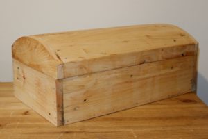
I’ve been keeping my toiletries in a plastic basket that I got at university, despite the fact the basket was way too small and things kept falling through the bottom. After having made a large treasure chest to keep my sheets and blankets in, I decided to take a second attempt at treasure chests and make a smaller, better constructed one from nicer wood.

I started with an interesting looking pallet that I found at work. It was stamped (always check your pallet stamps to make sure it’s safe to use!) as being from Germany, and I believe the wood to be birch or poplar (but I’m no expert). I kept the pallet in my garage for three months to acclimatise it to being indoors and avoid shrinkage.

To prepare the wood I broke the pallet down into planks, and knocked out the nails. Some of the planks split or were discovered to have splits during this process, so I filled the splits with glue and clamped the wood together. Once the glue was dry enough to work with, I ran all the wood through the thickness planer in batches, to expose clean grain on the top and bottom of the wood, and create planks of uniform thickness with parallel faces. I then used the table saw to cut the rough sides down, again in batches to keep the width uniform. After this I used the mitre saw to cut down the ends, and leave me with planks that looked like I’d bought them! (Apart from the nail holes.)

Once I had my wood together, I did a quick sketch on the whiteboard to work out how big my chest could be. I settled on the longest edge being the length of half a plank, which gave me a width of roughly 420mm, a depth of three plank widths (plus two plank thicknesses), or 230mm, and a height for the lower section of 100mm (1.5 plank-widths). This turned out to be perfect, leaving me only a couple of small scraps when finished!

Eager to start actually building the treasure chest, I started on the base. I cut three sections of plank, glued the edges, and clamped them to a workbench with quick release clamps to keep it all square. I screwed some scraps of wood to the planks so that I could remove the clamps and continue working while it was held together. I then cut the front, back and sides, carefully gluing along the plank edges. Using an engineer’s square to keep everything aligned, I tacked the pieces together with some brad nails and a small hammer. I then had a base.

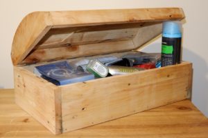
The lid required a curved shape. I got this by bending a piece of wire into the shape I wanted, and taping it to a plank. I then drew the shape onto the plank, and cut another identical plank. These were screwed together, cut along the line with the bandsaw, and smoothed by clamping the pieces in the vice and using the belt sander. I removed the screws, cut a plank in half and connected it to the front and back of each curved side piece, giving me the frame for the lid.

The curved top to the lid was created by first interlocking planks in a Roman arch style. I did this using the table saw’s angle cut function and an electronic angle finder. Each plank I fitted I cut to the correct angle to mate with the next plank, making sure that no part of the plank was below the contour of the curved sides. This worked well until the last plank, which needed a little bit of trial end error to get it to fit in as a “keystone”. Once all the planks were cut, I marked their positions, glued the edges, and tacked them into place from each end. This gave me a very lumpy looking lid with rounded ends. I used the rounded ends as a guide, and cut off all the protruding wood using the hand planer, before smoothing it with the belt sander and finally with sandpaper by hand.

At this point I returned to the base, glue now dried, and sanded down the edges with the belt sander, ensuring the external dimensions matched that of the lid – some back and forth was required as I removed imperfections. Once everything was smooth, I fitted a section of piano hinge with small wood screws, and oiled the wood using cooking oil – this works fine as long as you don’t get the wood wet, and means you can avoid buying oil just for wood!

The chest now sits on my chest of drawers in my bedroom. I’m not entirely happy with it – some of the split, glued planks are obvious, and the glue at the corners has gone grey where I watered it down for better penetration, but as a second attempt (and first at actually contouring the lid properly) I think I did pretty well – there are almost no gaps in the lid, looking almost like a complete, sculpted piece of wood. All in all it took me a couple of hours one evening to process the wood, and another evening to build the chest. I could have done it all in one evening, but I was working on other things at the same time and kept getting distracted! And of course, the cost was virtually free – the only thing I bought was the piano hinge, and I used roughly 1/4 of a £10 hinge.
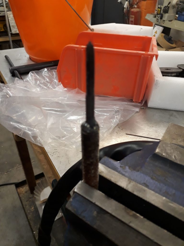
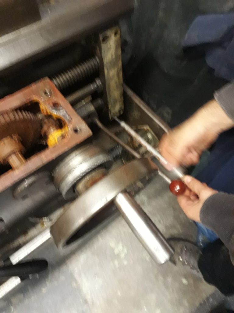
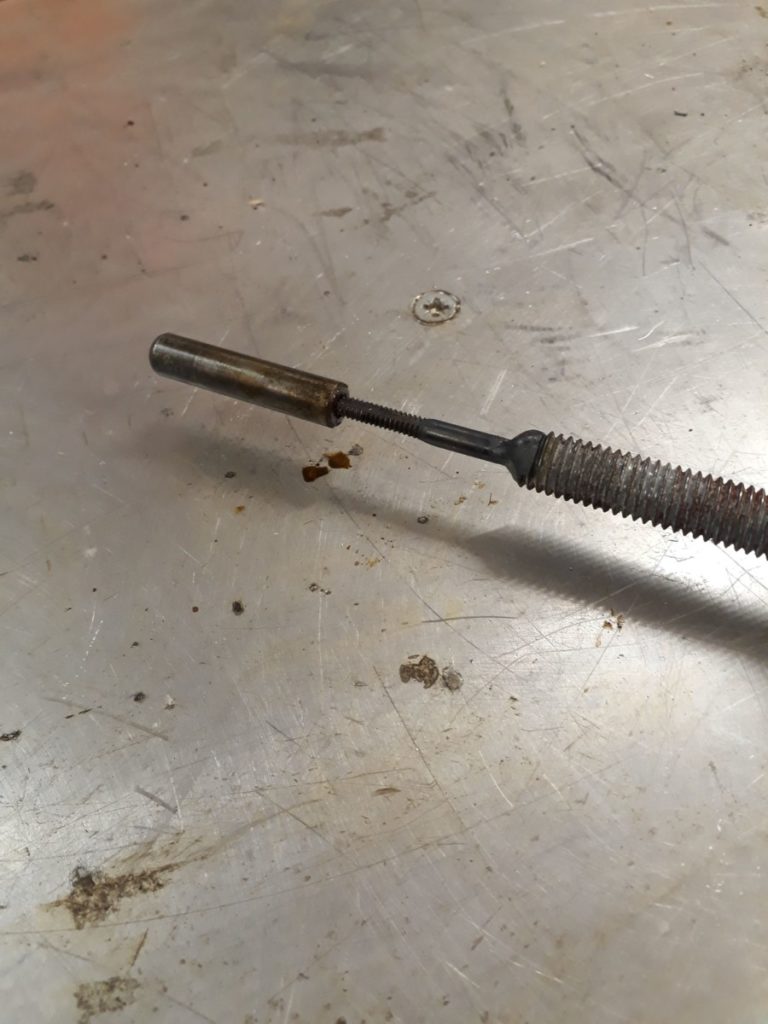
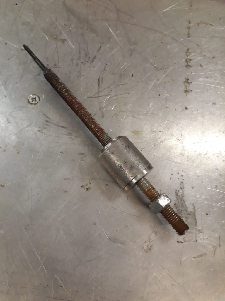
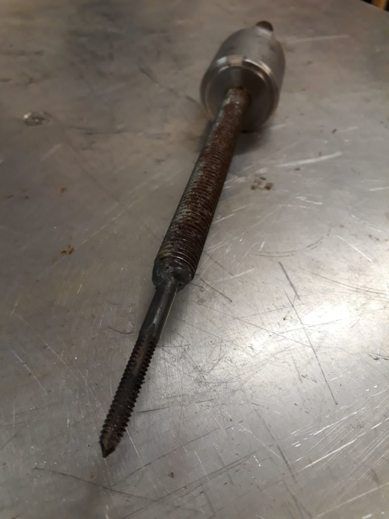
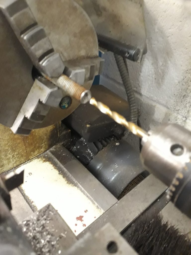
AUG 16 2018

Member Project: Dog food and water table

Stats
  • Made by: Jess
  • Status: Finished
  • Tools used: Mitre Saw, Powered Screwdriver, Trepanning Tool (new!), Polyurethane spray varnish

Description

My old dog is getting a bit unsteady, and often ends up sitting on her food and water bowls. The existing tray (which I added legs to a while ago) has gotten all soggy, and lost its bordering edge, so the water bowl ends up all over the floor.

The replacement needed to be more waterproof, taller, and keep the bowls in place, even when lent or sat on. I decided to cut circles out of the new top to sit the bowls in, and spray the whole thing with a waterproof varnish.

Trepanning Tool and holes in board

Trepanning Tool

The whole thing is made out of scrap wood from the Makerspace wood store. To make the circles I added a new tool to the space, a Trepanning Tool, which is attached to a powered drill and cuts a hole using two extra blades. It looks quite scary when spinning and takes a while to cut through the 6mm plywood. (Josh helped with this bit!)

The rest is assembled with legs cut to size and screwed together. The spray was the applied, which was dryish in an hour, and dry 24hours later.

So far it seems to be working, the doggo has only managed to slop some water, and not dump the whole thing on the floor.


Dog food and water table

Dog food and water table

This took me a couple of visits to the space, could probably have been done in one if I didn’t keep getting distracted. Some folks helped me out, which was good motivation. Now I don’t have to keep mopping the kitchen floor!


MAY 17 2017

Our TTN Gateway in Rapperswil is Live!

As you could read in our last two blogposts, we are currently experimenting with LoRaWAN, specifically with The Things Network. The LoRaWAN infrastructure is not built and provided by a single […]
APR 30 2017

LoRaWAN 868MHz Antenna Test (Part 2/2)

In our previous blogpost, we talked about ways to measure and compare antennas. If you haven’t read it yet, you should probably do so, unless you already know what antenna […]
APR 13 2017

LoRaWAN 868MHz Antenna Test (Part 1/2)

Over the last year, I started playing around with LoRaWAN, a long-range low-power wireless data transfer protocol. We internally crowdfunded a LoRaWAN gateway at Coredump and joined the Things Network. […]
APR 10 2017

Meine “Tour de Hackerspace”

Am 8. April habe ich mit meiner sechswöchigen Reise durch Europa begonnen. Mein Ziel ist es, dabei einige Hackerspaces in Europa kennenzulernen. Die Planung, wann ich wohin reise, geschieht mehr […]
MAR 24 2017

Making an OpenLog Serial Logger from Spare Parts

Part of our makerspace access system involves an Arduino and an ESP8266. Mostly it works just fine, but every now and again the Arudino seems to lock up and stop working. Various attempts have been made to stop this happening, but so far to no avail. Leaving a laptop connected to the Arduino’s serial port for debugging wasn’t happening because it happens quite infrequently and no-one had a spare laptop to leave lying around.

Enter the OpenLog! You can buy OpenLog boards for just over £10 (less if you are willing to pay the China-wait-for-delivery-tarrif) but where’s the fun in that? I remembered that I had an SD card reader breakout board languishing unused in a drawer (it came with my 3d printer kit and I’ve never gotten round to fitting it). And who doesn’t have some random Arduino boards lying around? It should be simple to make one right? right?

Nothing is ever quite so simple….

The Hardware

My first thought was that I’d need a 3.3V Arduino, because SD cards all run on 3.3V. Of course the Pro-Minis that I had were 5V; curses! Okay so I’ll need a level shifter as well but at least I have those. But wait! This SD card reader module is designed to connect to a RAMPS board that’s on an Arduino Mega and those things run at 5V…. On closer inspection the SD card reader module has a 74hc4050d IC on board, a quick bit of googling reveals that is a level shifter. Good, so I can use the 5V Pro Mini I have and the SD card reader module, but no need for another little board with a level shifter on.

IC1 is the level-shifter

Next problem, none of the pins on the SD card reader module are labelled! I could check the RAMPS pinout, but that’s somewhat confusing because the connector on the RAMPS has 8 pins and my module has 12. After a lot of scrolling through Google images I finally found one that looks to be the same and has the pinout at this link, so it’s an HCMODU0044.

Time to do some spaghetti wiring. Connect GND and 5V to, er, GND and 5V on the Pro Mini. Connect up SCK, SO and SI from the card reader to SCK (pin 13), MISO (pin 12) and MOSI (pin 11) on the Pro Mini. CS, what to do with that? Reading the main OpenLog sketch from their github repo, there is a handy define that SD_CHIP_SELECT is pin 10. That’s probably CS then, makes sense using pins 10-13.

Finally take a random LED and 22ohm resistor from the makerspace electronic parts stock and connect it to the other GND and pin 5.  This will be the status LED.

The Software

My plan here was to download the code from github and flash it.  Job done.  Nope, too simple!  It seems that the latest code (at the time of writing) doesn’t actually build.  Eventually I stumbled across this page which, as well being a good overview of using OpenLog, also contains a button to “Download OpenLog Firmware Bundle” about half way down the page.

This code compiled “better” than the latest from github, but still failed.  Downloading the latest Serial Port library, as directed on the OpenLog page and I finally had a version of the code that would compile.  This was using Arduino 1.6.8, the OpenLog page indicated they were using 1.6.5, so I suspect some incompatibilities have been introduced somewhere along the way.

Testing the OpenLog board using an FTDI lead and the Arudino serial console resulted in the text I typed ending up in a file on the SD card! Hurrah!

Final Thoughts

It had taken me maybe an hour to wire up and program, but that was after a couple of failed starts and a fair bit of rummaging around on the internet beforehand.  It seems like a useful debugging tool to have in your box of tricks, I’m not sure why I’ve never bought or put one together before.  It would be nice to build it onto a little PCB to tidy up the wiring, but that’s a project for another day….

Has it helped to fix the problem with the makerspace access control system?  We don’t know yet….