By Matt, Aidan, Derek, Jess & James
Tools at the Makerspace used:
MIG welder
Planer
Band saw
Mitre saw
Laser cutter
Soldering iron
various handheld tools
Concept and design
Each year the South Swindon Parish Council hosts a light trail at night though the Old Town Gardens. It’s a fun event where you get to walk though the gardens at night viewing different light installations from disco balls to multi-coloured arches and more. Back in the middle of September we approached the council with the concept of us making something for the light trail. We had about 8 weeks after contacting them and discussing initial ideas to design and build the whole thing, ready for it to be used on the opening night of 30th Nov
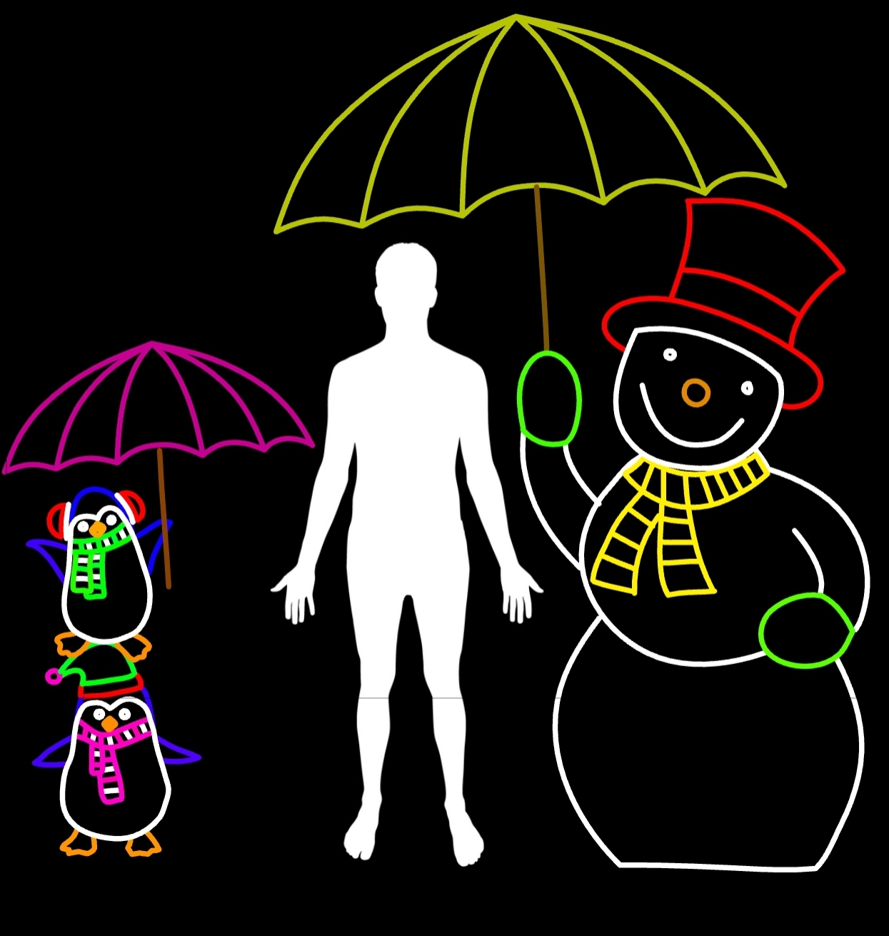
As a group we came up with a few different ideas. An infinity mirror dodecahedron, which while visually unique didn’t have much interaction. Angel or fairy wings, we would have like those on the trail to control the light patterns on these but that added too much complexity in our limited time window to make this. The design we ended up choosing was penguins and a snowman with umbrellas, originally it was going to be a polar bear rather than a snowman, but every polar bear we designed just looked like a normal bear painted white. While the 5 of us have plenty of varied technical skills none of us are amazing artists.
Now that we had chosen a design, the difficult question of how to make such a thing came to light. With the tip of the highest umbrella being 8 feet in the air we had to find a way to support it in a cost effective way that would be safe to leave in the park for 5 weeks straight. An early idea was large sheets of wood that we drilled holes in to position the LEDs in. This would allow us to draw the design on the wood and quickly drill holes across the entire thing, however it would also have it a giant sail and even with weights holding it down it would have likely blown over in the winter weather. In the end we decided upon a steel wire frame that followed the LEDs with a wooden frame that it all clipped to, to stand strong and light so that it could safely be in the park for over a month.
Building the steel frame
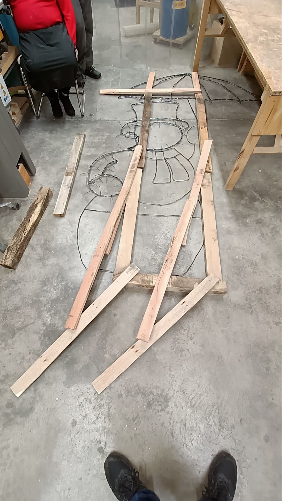
The initial design was scaled up to real world size and printed on our A3 printer at the Makerspace and we taped together groups of pages into each section so that they could be worked on concurrently.
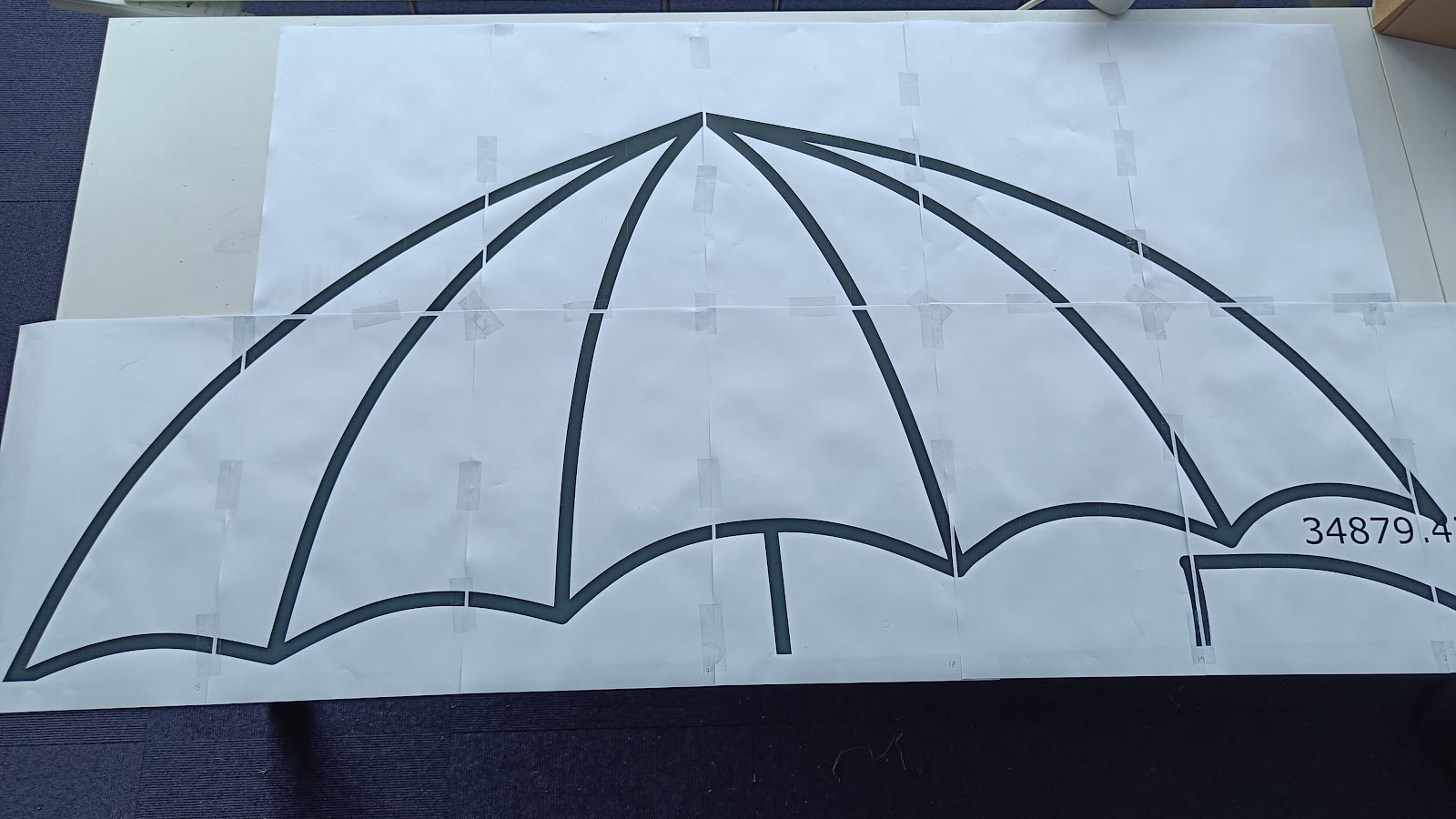

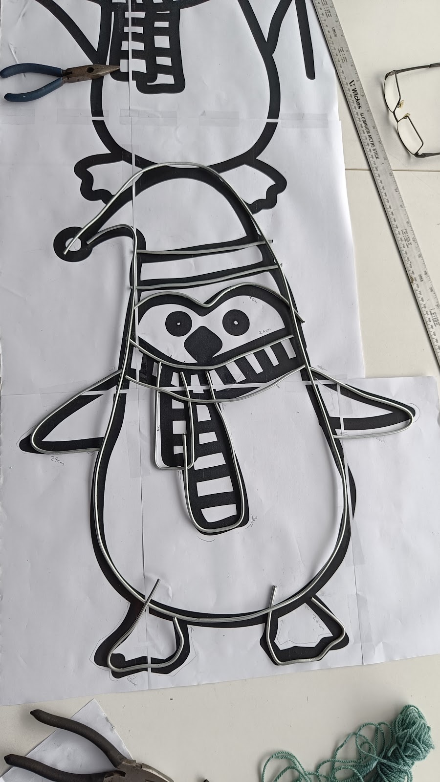
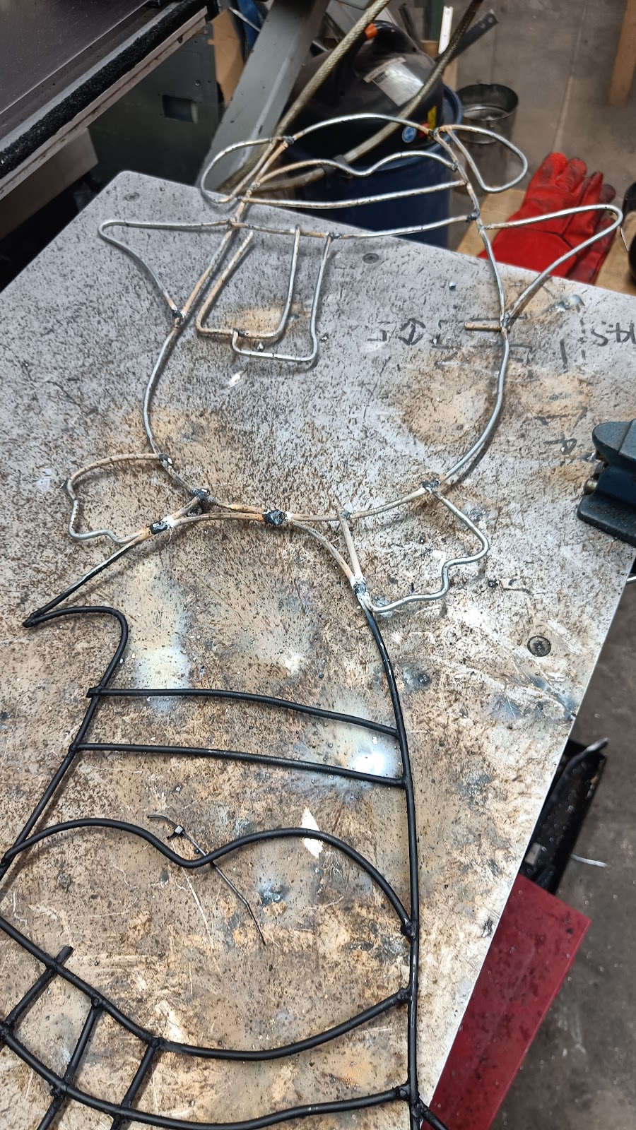
This gave us as a easy to follow template to hand bend the steel wire into before welding it together. once welded they were spray painted black
Don’t forget with galvanized steel, grind off the outer protection for better welding and not breath in some nasty fumes
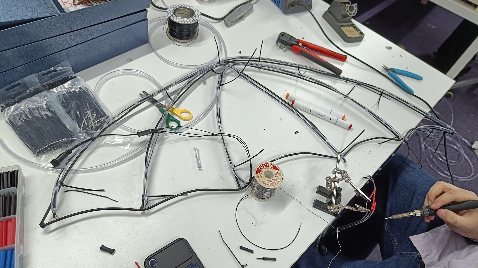
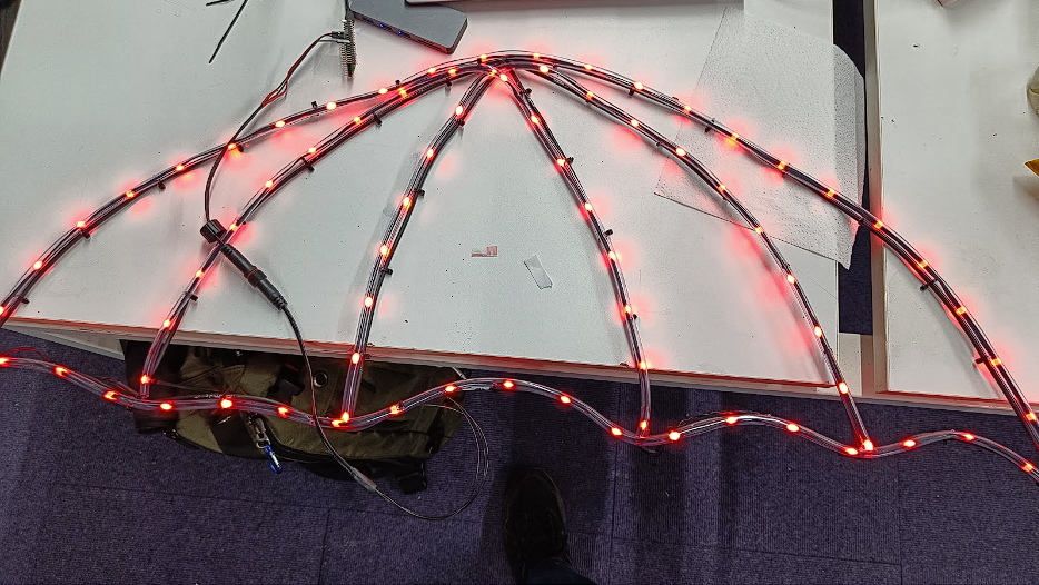
To help the LEDs light follow the shape of the penguins and snowman, we placed them inside some tubing as a makeshift diffuser. Sections of leds were then wired together and zip tied to the welded frame. We used addressable RGB leds (WS2811) which allowed us to control their colour in software which is mentioned later.
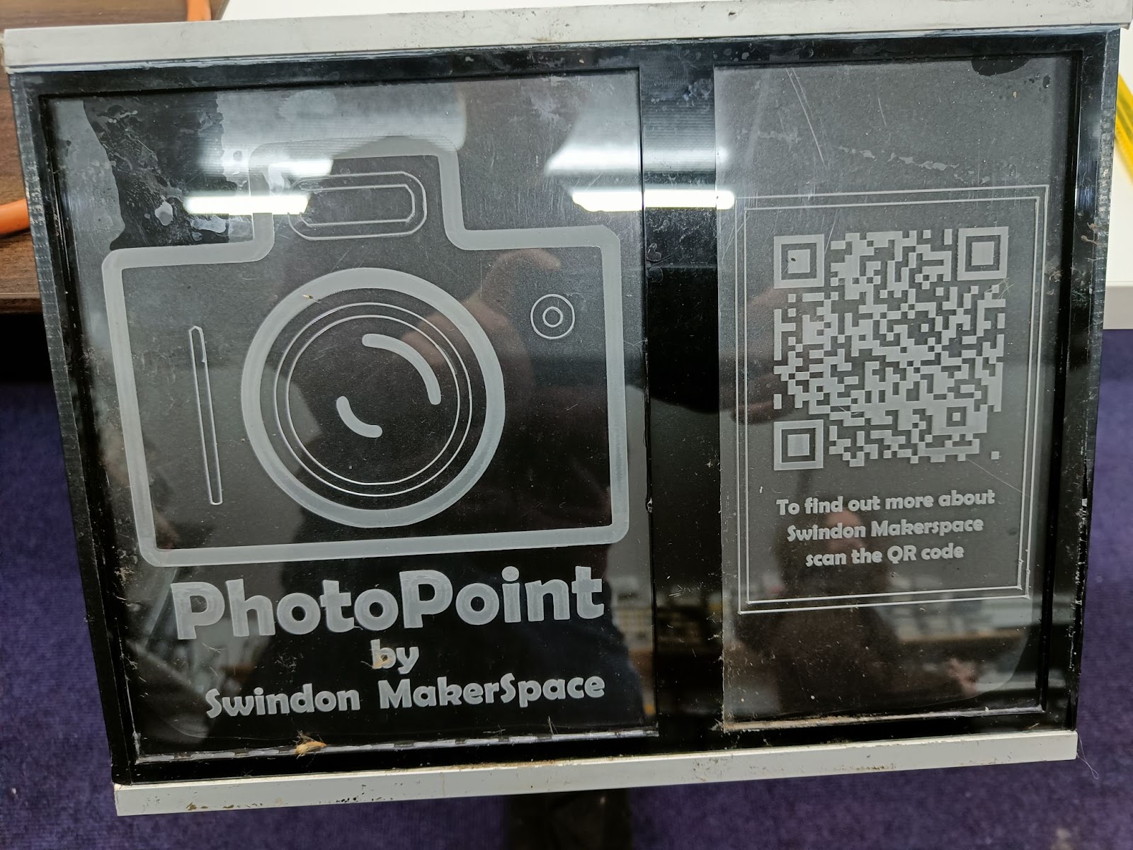
Makerspace badge & signage
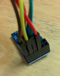
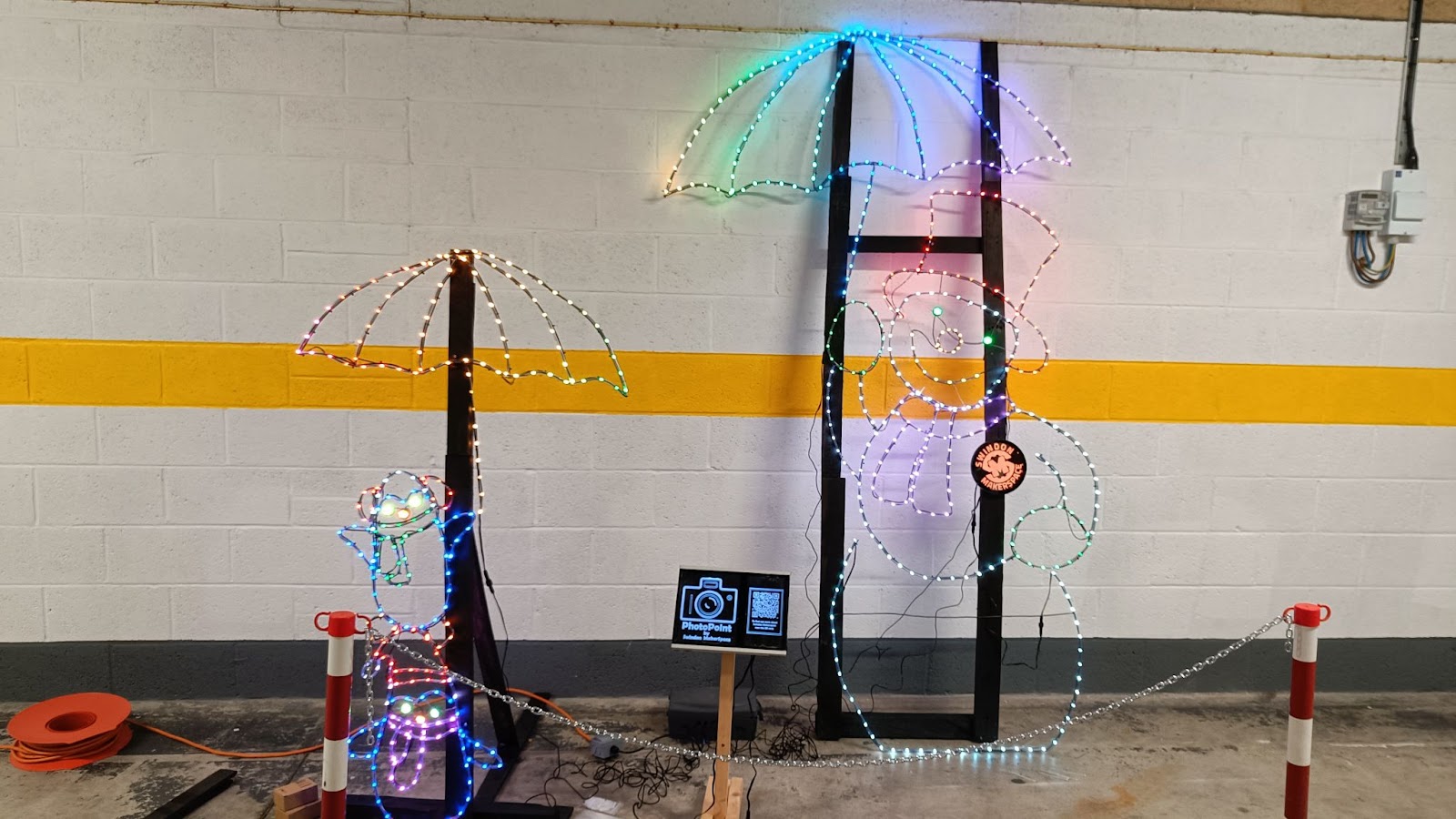
To help people recognize the Makerspace as the group that made the display we added a logo and a display. The logo was a badge for the snowman, we engraved the Makerspace logo onto some acrylic with the laser cutter we have at the space, this was then edge lit to help highlight the acrylic. The same technique was applied to the display stand with a QR code to our website so anyone curious enough to scan could find out more about us.

Standing Frame
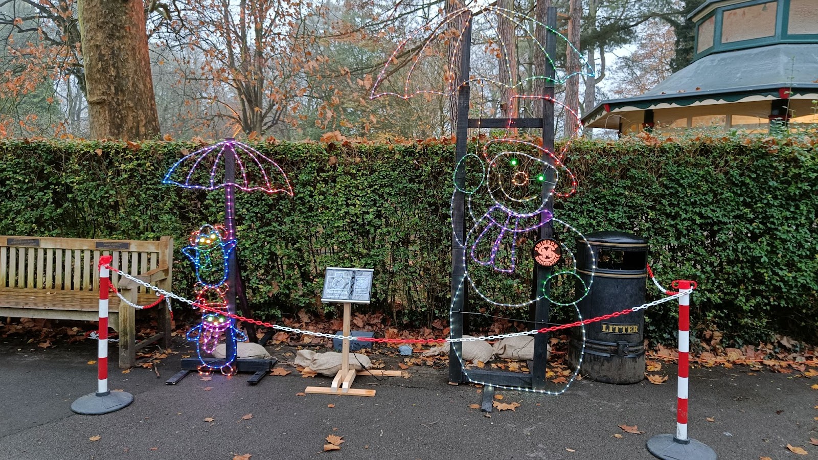
After a fair bit of muscle to bend the wire into shape, welding sections together and then zip tie all the LEDs in tubes in the frame, the next question came up. How does this stand upright in the middle of winter? We came up with the idea of a wooden support frame held down in position with sand bags.
To help keep costs down we up-cycled some wooden pallets. This involved breaking them apart, removing all nails, cleaning up the rough edges with the Planer/Thicknesser and then cutting to the desired length on the mitre saw. As the display was relatively light the frame didn’t need much support and a sandbag would prevent it from moving in the wind
Electronics and coding
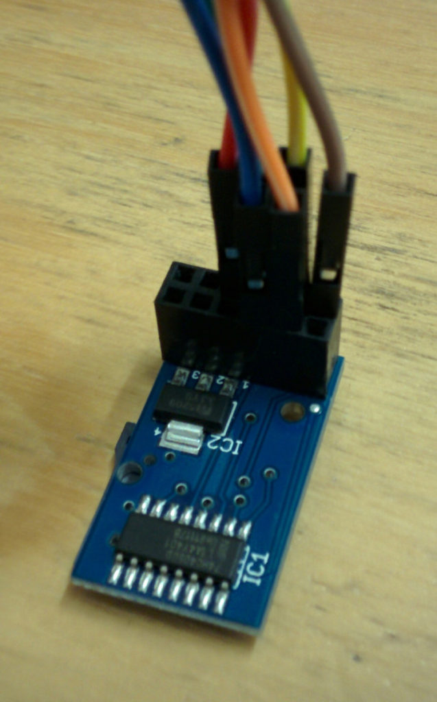
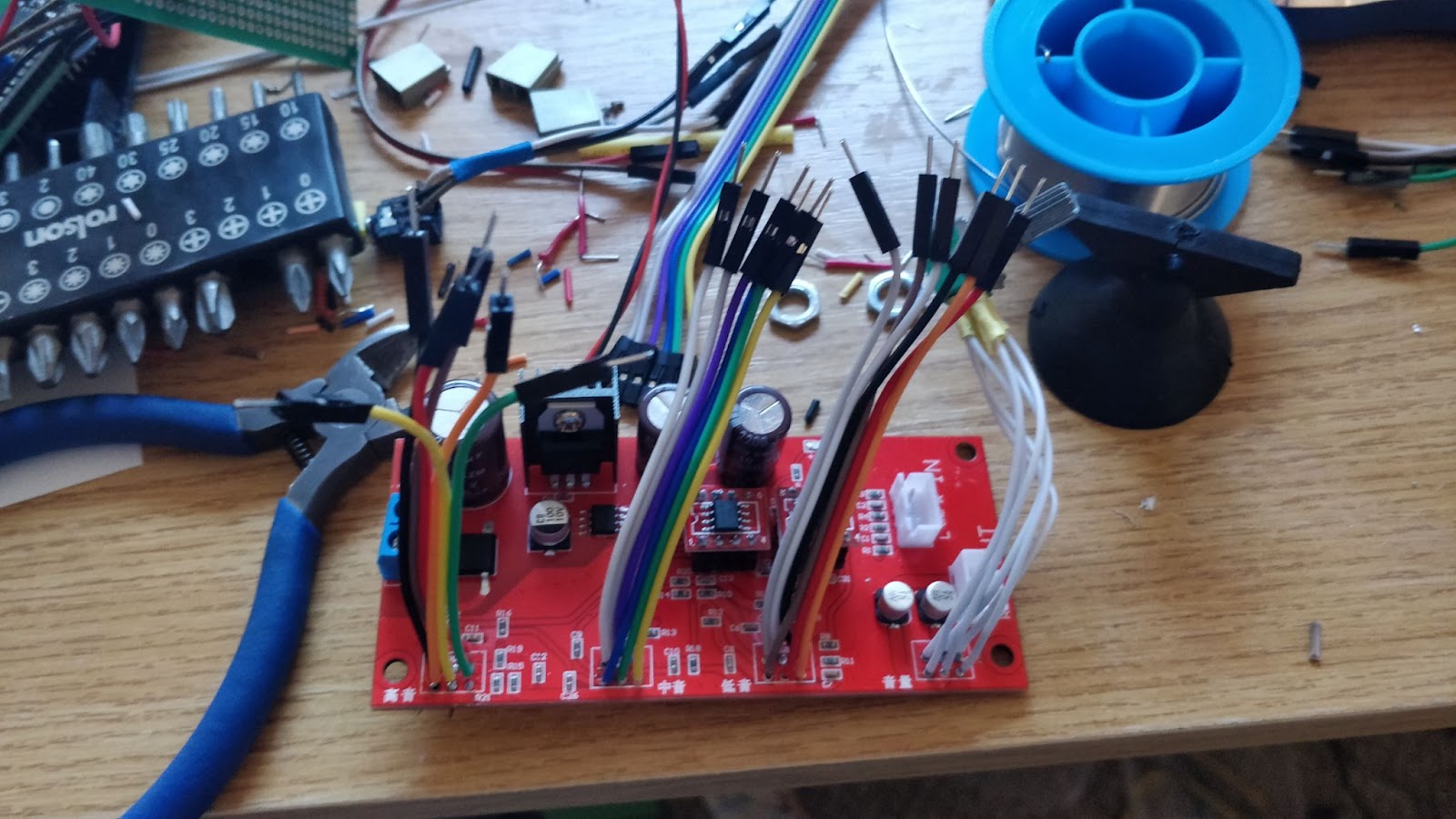
With over 700 LEDs each RGB and addressable presented a few issues but also some built in solutions. With LEDs being so efficient the power consumption was not too much to worry about however it could pull in excess of 10 Amps at their 5 volt operating voltage. They could have consumed even more but we limited their maximum brightness to prevent blinding guests who came to see the display. We found a cost effective way to power these with a many port USB power supply. To improve reliability the design was split into sections of around 100 leds each which had its own power rail from the power supply and separate data signal from the Teensy 3.6 micro controller that we used to control the LEDs.
The leds themselves are daisy chained WS2811, allowing for many to be controlled by a single data pin. Each section had its own data pin for ease of design. We initially wanted to use the Raspberry Pi Pico, however this had issues with the LED library we were using so moved over to the Teensy 3.6. The code didn’t change though as this was all written in arduino. For ease of programming the over 700 leds we programmed them block by block. Each block represented a visual feature of the display from penguin left foot to snowman nose. Then a colour was assigned to each block.
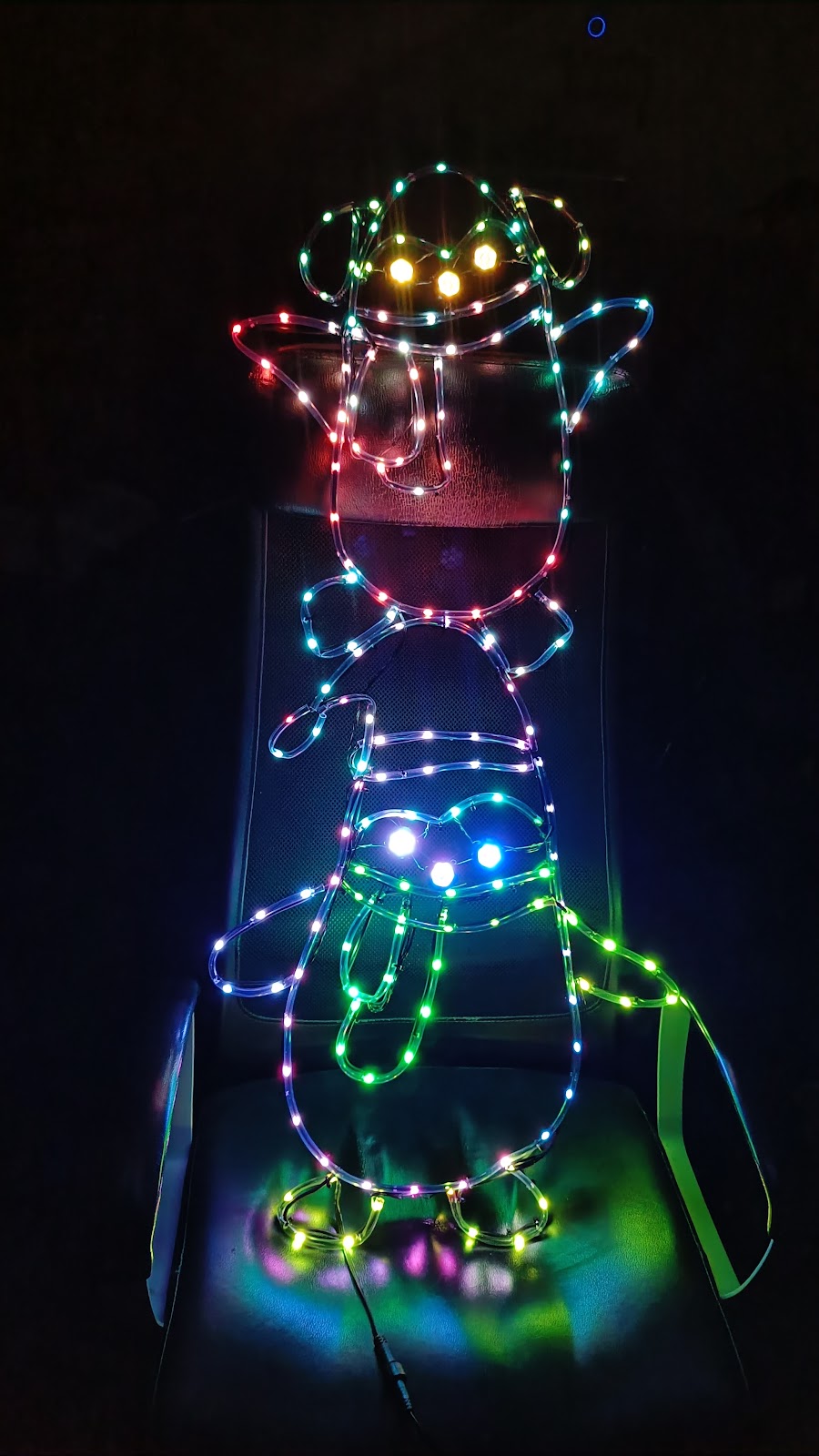
After programming all the sections we turned it all on but noticed a slight issue, colour correction
In the image above the snowman is meant to be white not purple and the eyes were not meant to be red or that bright. The first issue was caused by red and blue leds being much brighter than the green causing a tinting issue, this was fixed in software by setting white to be a pale green instead.
The eye colour presented a slightly different problem though. The eyes used different LEDs as they are premade circles of RGB addressable LEDs rather than the wire form we used on the rest of the design. These LEDs were GRB rather than RGB so when we set them to be green they turned red, and if we set them to be yellow they would be purple. As there were also 7 of these LEDs in such a small space we had to lower their brightness otherwise the penguins looked rather evil with such bright eyes
Final steps of building
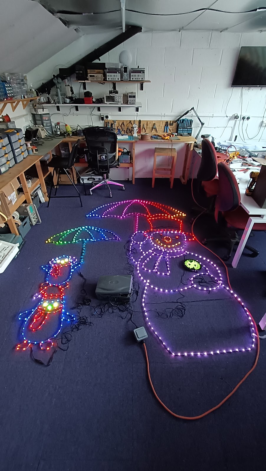
With the opening day happening on the 1st December time was beginning to run out so we hurried to get the final design built and make sure it all works. Each section had worked properly by itself but we had yet to put it all together. The day before we set it up in the Town Gardens we put it all together in the hallway outside the Makerspace before packing it all up in a couple of cars

So came the day for us to setup outside, this would be the first weather test of the display and over the whole 5 weeks it was outside we had very little go wrong which is a testament to the build quality of us here at the Makerspace
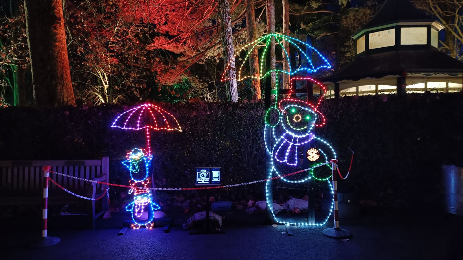
The light trail
Along came the opening night, it was really popular and the display itself looked amazing in the dark, the umbrellas had a slow wipe of rainbow colours across from side to side. We would have liked to animate the lights more but ran out of time.
It was great to see so many children and family take photos with our penguins and snowman
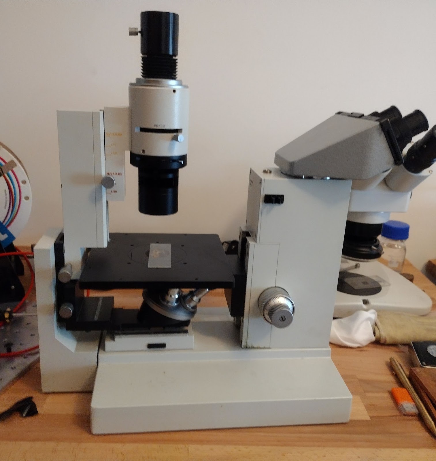
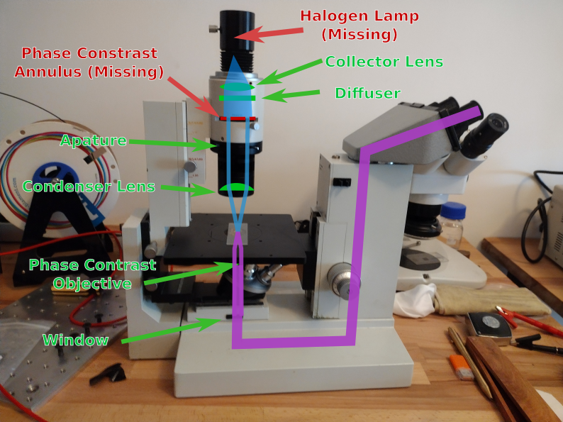
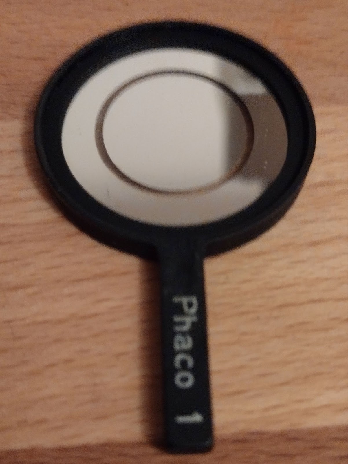
 Phase Contrast Annulus
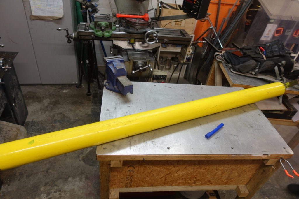 Scrap steel tube
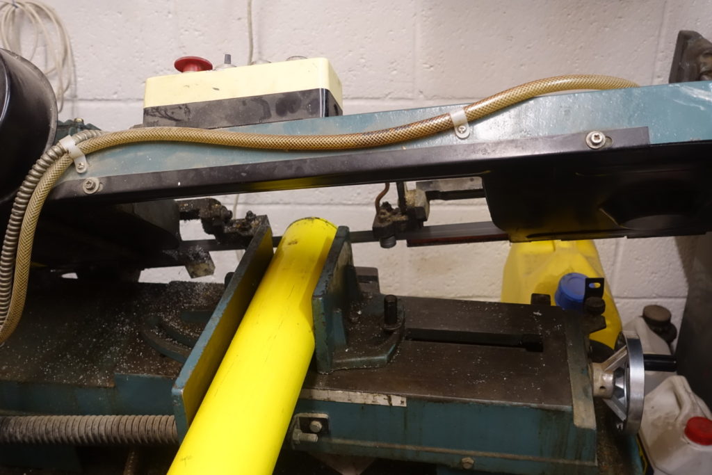 Cutting the ends off the tube with the bandaw
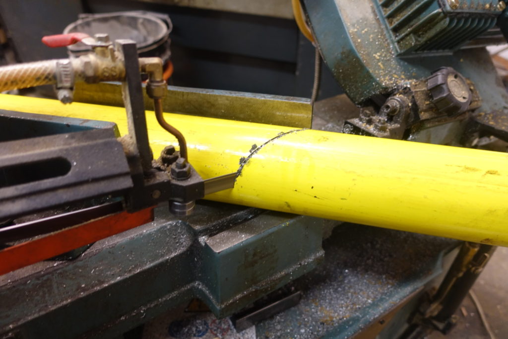 Mitre cutting on the bandsaw
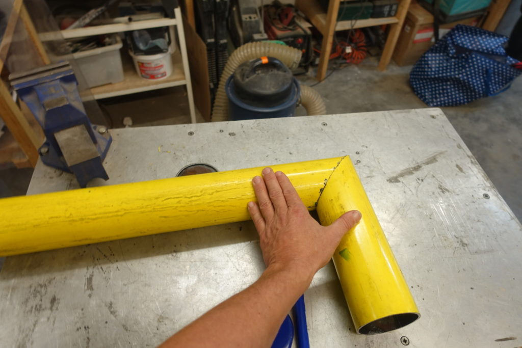 Successful mitre!
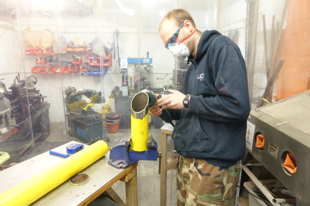 Stripping the paint with the grinder
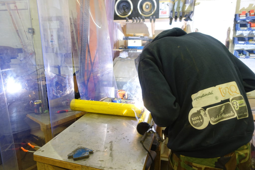 Welding the continuous bead
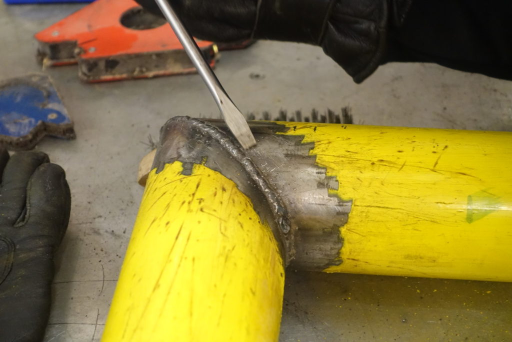 Bead after cleaning with a wire brush, while removing splatter with a screwdriver
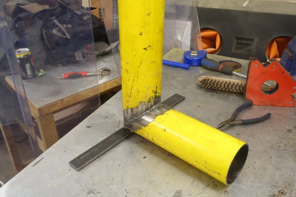 Foot welded to the base
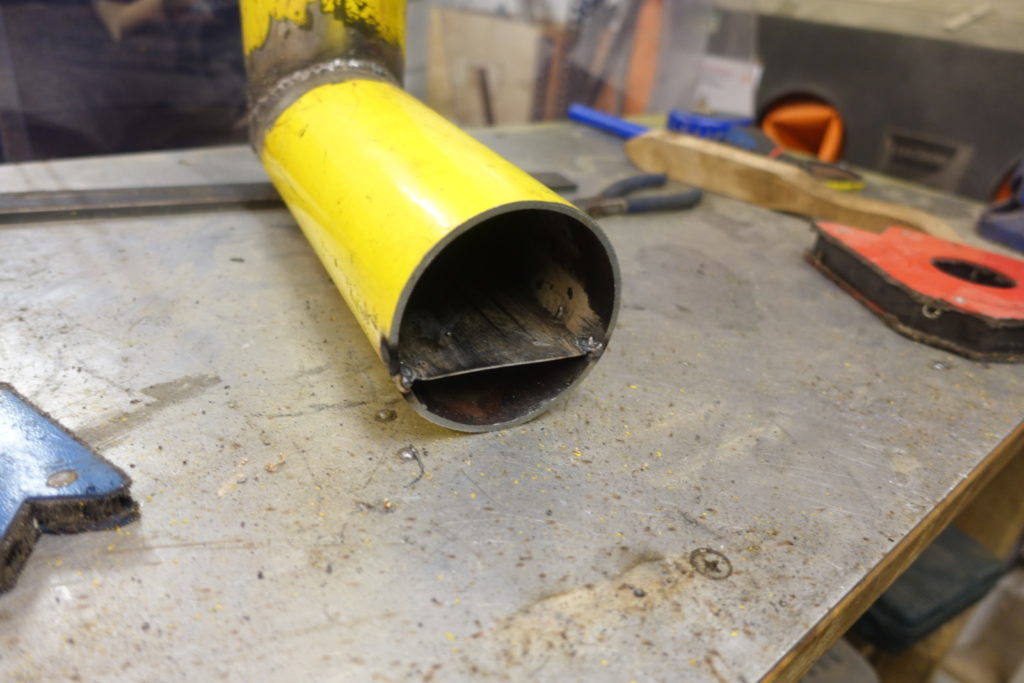 Tongue welded inside the tube
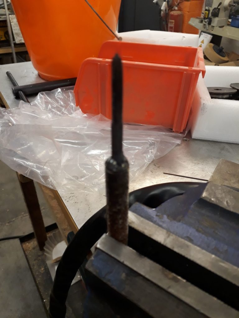
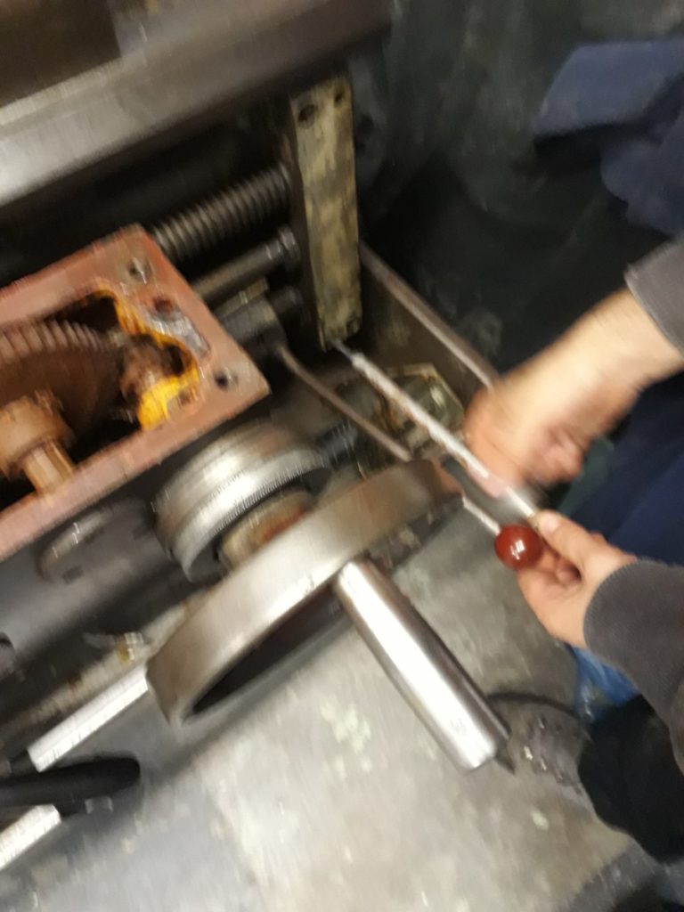
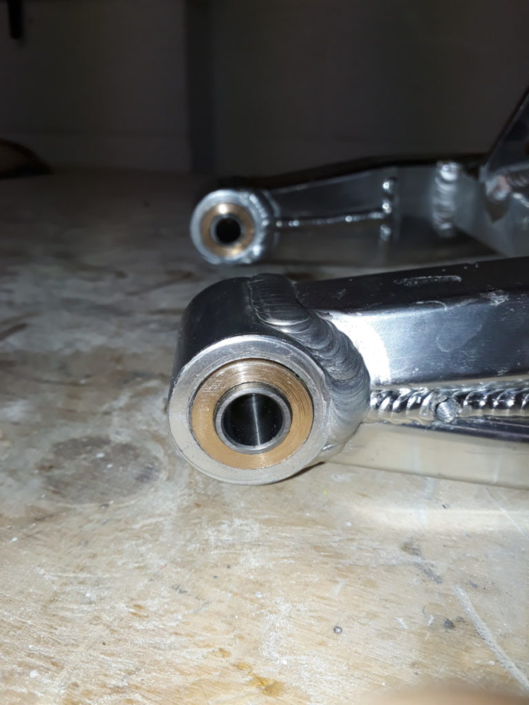
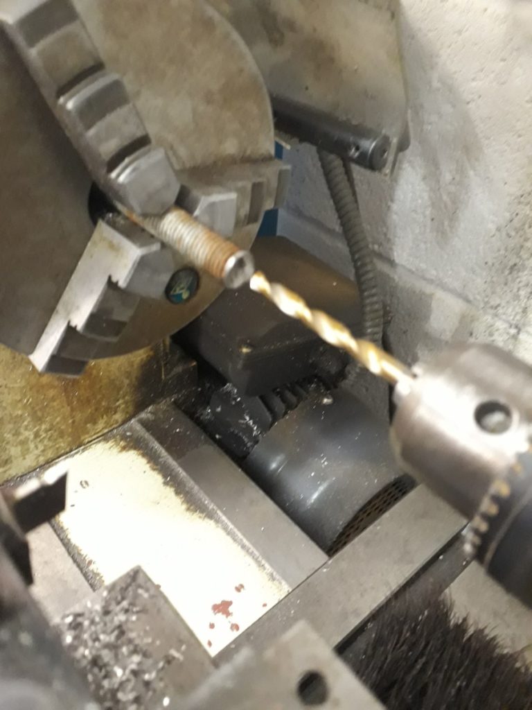 The screws were easy enough to remove, the dowels less so. They are an interference fit but have a thread in the centre to which it is intended to connect to and using a slide hammer pull them out. So the simple plan was to insert a bolt and pull them out, trouble was a M4 bolt was too small and a M5 had the wrong thread. Then it dawned on us, imperial. Trouble was at this point we had half disassembled the lathe and realised that we had neither an imperial bolt of the correct size, nor a slide hammer. Looks like we were going to have to MacGyver our way out of this one…

 Stats
Stats